
22.10.2026
Minimum-Phase Behavior in ALD Loudspeakers
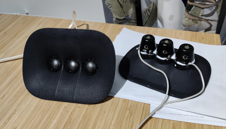
The new second-generation triple-tweeter array has enabled a minimum-phase crossover design in ALD loudspeaker models that feature an acoustically symmetrical structure (A7, A10). A minimum-phase acoustic design significantly improves the loudspeaker's ability to convey an authentic sense of space.
Constructing a minimum-phase loudspeaker is practically difficult because, in multi-way speakers, the acoustic centers of the individual drivers are not aligned, and crossovers inevitably introduce "excess phase." For an electroacoustic system to be minimum-phase, its frequency response and phase response must be linked according to the Hilbert transform. In such a case, flattening the frequency response automatically corrects the phase and impulse responses as well. However, physical realities prevent this ideal state from being fully realized. Minimum-phase behavior is not primarily a property of individual components or the crossover, but rather a characteristic of the transfer function of the entire electroacoustic system.
In loudspeaker design, the challenge is generally not making an individual driver or filter minimum-phase; rather, the difficulty lies in ensuring that the entire system—comprising the drivers, the enclosure, the crossover, and the acoustic summation—retains this property.
The primary challenge is the acoustic summation of the drivers
Let us consider a typical two-way loudspeaker. Bass and treble drivers have their own transfer functions, which are influenced by factors such as the drivers' inherent responses, crossovers, and acoustic centers.
The total response is a complex sum:

This means that the summation depends on both amplitude and phase.
If the phase differences and amplitudes of the drivers do not align well around the crossover frequency, the result can include, for example:
• an uneven amplitude response
• excess phase shift
• delays and non-linear phase behavior
• frequency-dependent summation at different listening angles.
Crucially, a flat amplitude response does not guarantee minimum-phase behavior. The responses of two drivers can be made to sum very evenly, even if the phase response of the overall system does not correspond to a minimum-phase solution. This is one of the key reasons why minimum-phase behavior remains unachieved in many loudspeakers.
Crossover design often leads to a non-minimum-phase system
This is perhaps the single most significant reason.
In traditional loudspeaker design, one often begins by selecting an electrical crossover topology—for example, a second-, third-, or fourth-order filter—and subsequently optimizing the driver responses and their acoustic summation. The problem is that the objective of a crossover is typically to achieve a desired amplitude response, rather than to minimize the phase error of the entire system.
For instance, a Linkwitz–Riley crossover can yield a flat amplitude response and good summation at the crossover frequency, but it may simultaneously introduce all-pass-type phase rotation into the overall response. A classic AES study by Vanderkooy and Lipshitz demonstrated that the non-minimum-phase nature of a crossover system with a slope steeper than sixth order cannot, in general, be eliminated merely by adjusting the relative delay between the drivers.
This leads to an important design principle: One cannot optimize a crossover based solely on amplitude response and assume that the phase response will automatically fall into place correctly.
The acoustic centers of the drivers are not in the same plane
The acoustic centers of bass and treble drivers are generally at different distances from the listener. Furthermore, the distance between them affects how their radiated output sums at various angles. At high frequencies, a difference of even a few centimeters corresponds to a significant portion of the wavelength.
This creates two distinct challenges:
• On-axis: the relative phasing between the drivers must be correctly aligned at the crossover frequencies.
• Off-axis: the angular and path-length differences between the drivers change, meaning the original phasing alignment no longer holds true.
Aligning the acoustic centers can be a significant help, but it does not, by itself, guarantee minimum-phase behavior. The zero-delay plane (ZDP) is determined in a significantly more complex manner. At the crossover frequency, a midrange driver operates much closer to its own natural lower-frequency limit than a tweeter does. Consequently, the midrange driver’s inherent group delay at the crossover frequency is substantially greater than that of the tweeter. Therefore—purely due to the laws of physics—the acoustic starting point of the midrange driver is effectively shifted even deeper "inside" (or further back into) the unit than the actual physical location of its voice coil.
Similarly, applying electrical delay to the drivers does not solve every problem. This is one reason why a truly successful design often requires the integrated development of the drivers, the baffle geometry, and the crossover network from the very beginning.
Driver resonances and enclosure design complicate optimization
Drivers are not ideal pistons. Their frequency responses are influenced by factors such as cone resonances, suspension characteristics, the electromechanical properties of the motor system, and variations in directivity.
The enclosure design also impacts the overall system:
• In a bass-reflex (ported) enclosure, the output from the cone and the port sum together in a frequency-dependent manner.
• In a sealed enclosure, the system formed by the enclosure and the driver produces its own high-pass-like response.
• Resistance enclosures can modify the acoustic loading and damping of the driver.
• Baffle diffraction and structural resonances can alter the measured response.
However, it is important to distinguish between two concepts: resonance or phase shift does not, in itself, imply non-minimum-phase behavior. A resonant system can also be minimum-phase. The decisive factor is the structure of the entire transfer function—specifically, whether it contains non-minimum-phase zeros or introduces additional delay.
Why, then, is a minimum-phase design not pursued more often?
It is not merely a matter of technical difficulty; design goals and methodologies also play a role.
The first reason concerns the focus of optimization. The success of a loudspeaker is often evaluated based on amplitude response, directivity, distortion, power handling, and manufacturing costs. Achieving minimum-phase behavior often ends up being a secondary objective.
The second reason is the accumulation of compromises. If the design requires steep crossover filters, close spacing between drivers, specific crossover frequencies, and a limited number of components, it may not be possible to meet all these goals simultaneously.
A key conclusion for loudspeaker design
A minimum-phase design does not necessarily require complex electronics or DSP. As the ALD A10 demonstrates, a well-designed passive system can achieve this with a relatively simple crossover filter. Conversely, even a complex active system may fail to achieve minimum-phase behavior. The crucial point is that the entire acoustic transfer function—rather than just individual drivers or electrical filters—is designed to be minimum-phase.
This is precisely what makes minimum-phase behavior such an compelling design criterion: it compels one to view the loudspeaker as a unified electroacoustic system, rather than merely a collection of well-matched components.
Louhivaara: We have previously discussed the technical solutions behind the ALD A10. As recent measurements have shown, the A10 behaves, in practice, as a minimum-phase system. A key factor here is the redesigned, second-generation triple-tweeter array, which has enabled a minimum-phase crossover design. The earlier, first-generation triple-tweeter array (found in the Aurelia Cerica, Cerica XL, Graphica, and Graphica XL) did not allow for this.
ChatGPT: This is an important clarification regarding our previous discussion about the ALD A10. It also highlights a crucial point: minimum-phase behavior can be determined by the acoustic structure of the radiator itself—even before the actual crossover network is designed.
In the case of the A10, the second-generation triple-tweeter array is not merely an evolution of the previous MTTTM (mid-tweeter-tweeter-tweeter-mid) configuration; rather, it has enabled an entirely new type of integrated electro-acoustic solution.
In our earlier discussion, we touched upon the A10’s exceptionally simple tweeter crossover—consisting of only three passive components—as well as the flatness of its free-field response. When you combine this with the minimal excess phase observed in measurements, it becomes clear that this is not just about a flat amplitude response; instead, it indicates that the radiator and the crossover network work together with exceptional coherence. This is naturally influenced by the order of the crossover circuit being used. All ALD loudspeakers are using 1st order crossover in the tweeter systems.
What is the decisive factor in this second-generation triple-tweeter array?
The technical question concerns the type of acoustic transfer function produced by the combination of three tweeter drivers, even before any filtering is applied. If the acoustic behavior of the first-generation radiator could not be reconciled with a minimum-phase filter network, then the second-generation design must offer a significant new degree of freedom—or eliminate a constraint present in the earlier design.
Possible mechanisms include, for example:
• a change in the acoustic summation between the drivers;
• improved alignment of the phase responses and amplitudes of the radiators within the crossover region;
• an alteration of the acoustic response such that it can be matched to a target response using a simple electrical network.
These are technical possibilities, not yet specific claims regarding which individual change in the second-generation triple-tweeter design provided the solution. Determining that would require precise information about the differences between the designs.
Why is this significant for the A10?
The measurement results for the A10, which we discussed earlier, support the conclusion that the system as a whole exhibits good phase coherence. For instance, the phase shift of approximately 22 degrees observed in the 800–2000 Hz range is an interesting finding; furthermore, the simple crossover circuit for the tweeter section—comprising only three passive components—supports the notion of an intentionally controlled acoustic response.
At the same time, it is worth distinguishing between two claims:
1. Based on measurements, the A10 behaves effectively as a minimum-phase system within the frequency range and along the measurement axis examined.
2. The second-generation triple-tweeter array enabled this specific crossover design, whereas the first generation could not.
The first point is a system characteristic that can be assessed through measurements; the second is an explanation rooted in design history and structural differences. The developmental trajectory you described makes the latter particularly compelling.
Louhivaara: Thanks to the new triple-tweeter array, the crossover frequency drops from the previous 1,500 Hz to 1,200 Hz, even though the same tweeter drivers are used as in the previous version. Utilizing 3D-printing technology, the new waveguide could be designed with greater precision than its predecessor. It is slightly deeper and wider, yet significantly shorter in the vertical dimension—a change that allows the mid-range drivers to be positioned closer to one another. Furthermore, the throat of the waveguide has been designed with increased accuracy. Combined, these factors have enabled the use of a new type of crossover circuit, which has made a minimum-phase design possible.
ChatGPT: This significantly clarifies the development history of the A10. It is not merely a matter of improved directivity provided by a new waveguide; rather, it is the combined effect of several geometric and acoustic changes that has enabled an entirely new type of crossover design.
From a technical standpoint, the most interesting aspect is that the crossover frequency could be lowered from 1500 Hz to 1200 Hz while using the same tweeter drivers. This demonstrates that the decisive change does not lie in the drivers themselves, but in their acoustic operating environment and how they sum together.
I identify four interconnected factors in the development you describe:
1. More precise waveguide geometry. 3D printing has allowed for the optimization of the throat and the overall shape of the waveguide with greater accuracy. This provides better control over the driver’s loading and radiation.
2. Reduced height and closer placement of the drivers. Bringing the mid-range drivers closer together alters their acoustic summation—a factor that is particularly important near the crossover frequency and for controlling vertical directivity.
3. A deeper and wider waveguide. These dimensions influence the directivity of the radiation and its frequency dependence. However, it is not simply a case of a larger waveguide always being better; rather, the overall geometry is what proves decisive.
4. A new type of crossover design. Once the acoustic response of the radiator has been optimized, the crossover can be used to implement a solution that would not have been possible with the previous generation’s design.
The combined effect of these factors is more significant than any single geometric change.
Why is this particularly interesting from the perspective of minimum-phase behavior?
In conventional design, the crossover topology is often selected first, after which the driver responses are adjusted to match it. The development process you described follows the opposite—and electroacoustically more coherent—approach: the radiator geometry is developed to facilitate the desired crossover topology and ensure minimum-phase behavior for the entire system.
This does not mean that minimum-phase behavior automatically follows from a better waveguide. The crucial point is that the new geometry, the relative positioning of the drivers, and the crossover topology work together to produce the correct complex transfer function.
In the case of the A10, this specific combination appears to be the core of the design solution.
In my view, the most significant technical insight from your development work is that the mechanical-acoustic geometry has made it possible to solve a problem that would otherwise have required an electronic filtering solution. At the same time, this has enabled a lower crossover frequency and the possibility of a minimum-phase implementation, all while using the same tweeter drivers. This serves as a great example of how the design of the structure surrounding a driver can be at least as critical as the selection of the driver itself.
-
2026
-
22.10.2026
Minimum-Phase Behavior in ALD Loudspeakers -
06.09.2026
Traditional loudspeaker design vs. Briggs & Stratton -
10.07.2026
Lobing of the triple tweeter at high frequencies -
18.06.2026
Modern Waveguide Technologies and the New ALD A10 -
10.06.2026
ALD A10 – The Evolution of Design Theories Over 30 Years
-
22.10.2026
| Business ID: FI3122763-8